Posts: 225
Threads: 4
Joined: Sep 2008
Reputation:
0
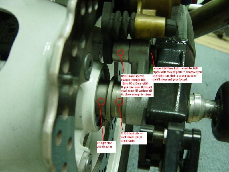
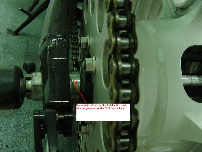
KAWASAKI 636 (03-04) REAR WHEEL SWAP :
 SWINGARM SWAP :
It is very simple, all you have to do it take out the rubber seal on the right side of the 05 swingarm and swap it for the one from the 03/04....That will allow you to use the threaded adjuster nut from 03/04 swingarm, so swap the seal use the 03/04 adjsuter nut and piviot shaft. Bolts right up.
YOU MUST ALSO REMEBER! That if your using the 05+ swingarm then you need to make sure the cush drive spacer on the left side must also be 05+. The cush itself is the same but those spacers are difernt widths, so if you use the 03/04 spacer with a 05+ swingarm your chain will be out of alignment. And vise versa
Then comes the shock! If you use the 03/04 stock and linkages then nothing needs to be done, however if you want to use the 03/04 knuckle with the 05 shock you need to swap the bottom(where the bottom shock mount bolt goes) 2 seals and bushing from the 05 knuckle into the 03/04 linkage. Because the 05 shock eyelet on the bottom is a little narrower, so for it to fit those need to be swapped. The knuckle and its roller bearings are the same but the 2 seals and bushing are differnt widths...If you have the 05 knuckle then it will all bolt right up. Also do not use the 05 upper mount (the steel part that mounts the shock to the frame, 05 is dark colour and 03/04 is silver, use the 03/04 on the 03/04 frame no matter what shock you use)
MADE BY JohnnyP
Posts: 225
Threads: 4
Joined: Sep 2008
Reputation:
0
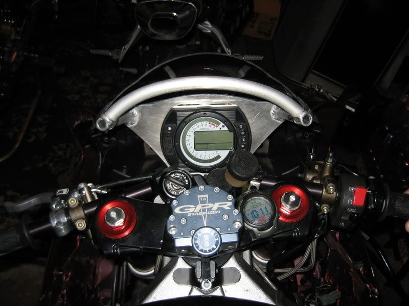
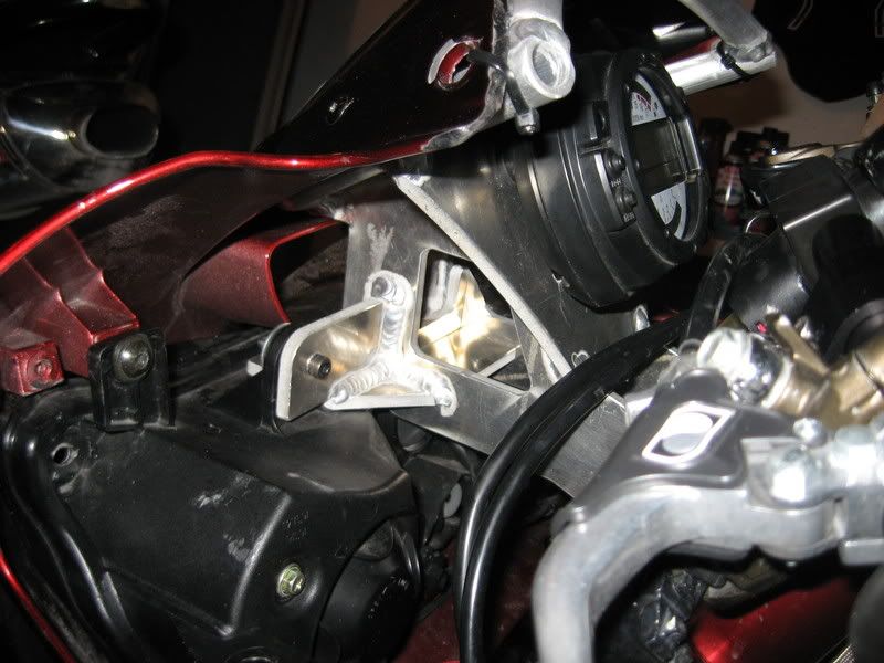
JohnnyP STUNT STAYS :
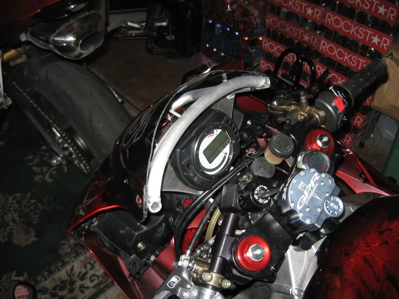
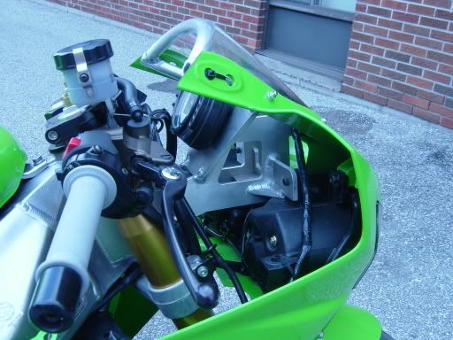 Click here to contact JohnnyP :
JohnnyP
Click here to contact JohnnyP :
JohnnyP
Posts: 225
Threads: 4
Joined: Sep 2008
Reputation:
0
NEW 636 SICKINNOVATIONS CAGE DESIGN :
We have recently heard several people with suggestions on some needed changes to our cage designs. Some of them were to use a larger diameter tube for the mounts so the cage would no longer eat sockets. Others were about the integrity of the cage and sliders. We completely revamped the 636 cage last night and today and are very happy with what we have to offer. At first glance it appears to be the same, but is quite different. For starters, we increased the mount tubing to a much larger diameter so no more stuck sockets! We also changed the sliders so they have a much larger diameter that goes into the mount so they will be much stronger. We also changed to a different material that has a much higher tensile strength so they ownt break off like they had in the past. Best part of it is that they now come included with the cages at no additional cost! Next we changed the lower tube. It was a vulnerable weak spot in the design of the 636 cage so we extended it all the way back to the rear mount. They will not bend there anymore. Next we upgraded the tubing from electric weld to DOM which is a much stronger tube. The lower mounts also changed which will make the installation much easier and will also make it easier to notch the fairings accurately. Lastly, we swamped out the rear all thread rod for a beefy solid rod that is threaded. These were some much needed changes and we appologize that it took us thisa long to make them, but the cages should match our expectations of this company.
In this first picture it shows the old design. I have circled the weak point in the cage design. The cage would bend upwards at the top tube just between the rear mount and where the lower pipe welds in. In the pic below, we extended the lower tube all the way back to the mount which will prevent the top tube from bending.


In thie 2 pics belwo show the changes we made to the lower mounts. The old design had a short mount on the right piece and a long mount on the left piece. The new design, both cage sides have short mounts and there is a piece of 1in dom tubing that is threaded so you simply run a bolt through each end . This makes notching the fairings much easier and will ultimately make the whole install process that much quicker and easier.


The next pic is a close up of the lower tube that connects the 2 sides.

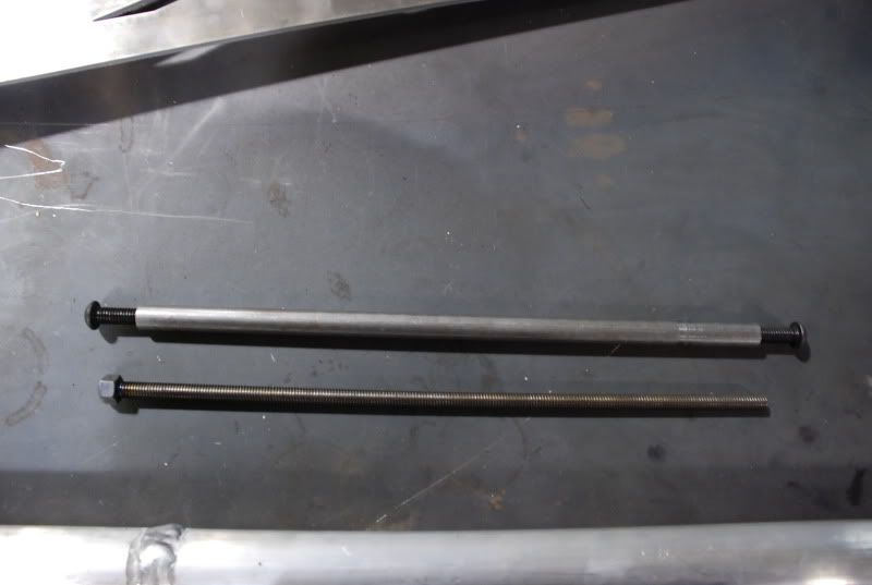
This pic below shows the all thread that the old design came with and the new solid rod that will be included with all the new designs.( the rod can be used with the old design as well.)
In this last picture it shows a comparison of the old style and new style slider. MUCH MUCH stronger due to the bigger diameter and we are using Nylon instead of the weaker Uhmw that we have been using.

Posts: 225
Threads: 4
Joined: Sep 2008
Reputation:
0
RIGHTEOUS STUNT CLUTCH LEVER :
The Righteous Stunt Clutch is an easy pull style clutch assembly that is milled completely out of billet aluminum. The RSC is designed very similar to the other easy pull style clutches on the market, but with a few changes that make the Righteous Stunt Clutch virtually bulletproof.
The three cable positions usually found on an easy pull style lever are eliminated, leaving only the one "easiest" pull setting. The swivel adjuster on the perch has also been eliminated, leaving you with a unit that is made out of MUCH stronger material with a much more straight forward design. We have eliminated ALL of the weak points of the competing easy pull assemblies, and have also closed up many of the SLOPPY tolerances found in them.
The perch has been designed with a rear mounting cap, which is also a much stronger design than the competition. The perch cap is also designed to be mounted flush on top, eliminating the unsightly "gap" found in most rear mounting assemblies. The ENTIRE unit is actually thicker and beefier than the competing easy pull units, while still keeping in mind the tight tolerance we encounter around our handbrakes as stunters.
The basic Righteous Stunt Clutch comes with a delrin bushing pressed into the lever. Delrin is an excellent material used in many bushing applications. Delrin also has a "self lubricating" quality to it, similar to Teflon. We use a bushing in the base model RSC to keep costs down while still providing silky smooth, buttery operation. An extra bushing is included with your order. We WILL be offering the bearing as an option, however, in the RSC Ultimate lever very soon. This assembly does have a lever distance adjustment set-screw to personalize your setup. All RSCs are assembled with stainless steel hardware.
The first run of Righteous Stunt Clutches are ONLY available in the "shorty" lever option, with the delrin bushing. Full length levers and bearing options will be available soon, as well as anodizing.
All orders are shipped via USPS Priority Mail w/ delivery confirmation.


 $ 83
$ 83 Shipped w/in the US $ 90 Shipped worldwide
http://www.righteousstuntmetal.com
Posts: 225
Threads: 4
Joined: Sep 2008
Reputation:
0
C4 - revolutions Tank dent and body work :
There has been a lot of questions on if we do paint and body work and or tanks dents.
C4 dose it all we make the stunt parts and paint bike and Yes we even dent the best tank dent in O-town.
Riders with are tank dents
T-neck,Cutler,Mich Adams,Jesse toler,Papa willy And a lot more
We have a deal going on right now for two types of tank dents.
1 st you ship or drop off your tank already dented and we shape it and add a 3/4" lip to the top and smooth the tank and put it in primer for $125.00
2 nd You ship or drop off your stock tank and we will dent it and smooth it and put it in primer for $125.00.
IF you want both done dent and lip add at the same time it would be $165.00.
Customer takes care of all shipping you ship UPS to us and buy the return label put it in the box and when the tank is done we put the label on the box and it ships back.
 www.c4-revolutions.com
Posts: 225
Threads: 4
Joined: Sep 2008
Reputation:
0
A-Town Customs Replacement Subframe for 2003-2005 R6/2006-2008 R6S :
Product Information :
If you expect to stunt your '03-'05 R6 or '06-'08 R6S then you better consider getting a replacement subframe for it. The stock subframe is cast and will break right away when you try to scrape or come back on the tail a little hard. A-Town Customs has come up with one of the strongest solutions available for your R6; This complete replacement subframe fits perfect and allows you to retain your factory battery tray and all! It comes professionally powercoated gloss black and will take all of the abuse you want to throw at it.
If you want you can add a Round Bar from A-Town Customs that will fit this subframe perfectly. Please add it to the below options.
Price : $359.95
Posts: 225
Threads: 4
Joined: Sep 2008
Reputation:
0
Posts: 225
Threads: 4
Joined: Sep 2008
Reputation:
0
Posts: 225
Threads: 4
Joined: Sep 2008
Reputation:
0
Rebuild your forks (F4 or F4i) :
Fork rebuild seal leak front suspension.
This applies directly to F4 and F4i forks since their construction and internals are identical (Only difference between the two is the fender mounting points). This is pretty easy to do, and will save you a couple hundred dollars over having a shop do it for you.
The tools you will need for this are:
- 24mm wrench or socket
- 14mm wrench x2
- 8mm allen wrench that you can apply a lot of torque
- A couple small flathead screw drivers
- A seal driver (see below on how to make your own)
- Access to a table vise
Things you'll need from Honda:
- Fork Oil
- New Seals
- New Bushings
- Revalve
- New Spring
Let's get started, first with the forks still in their clamps break loose the 24mm nut on top

Loosen it just until you can see the start of the o-ring coming out.
Next remove the forks from the bike. Loosen the front axle, remove front fender,remove calipers, remove front axle, remove front wheel, loosen upper and lower clamps, removehandlebars,slide forks out of the clamps.
Now, keep everything organized and keep your forks seperated, no mixing parts.
With the forks removed unscrew the top 24mm nut the rest of the way, it is spring loaded, so when the last thread is undone it will kind of bounce a little.
You should be looking at this:

Put a 14mm wrench on the bottom nut

While holding onto that nut unscrew the big 24mm nut all the way off. If the part in the middle starts spinning try grabbing the top adjustment piece with the 14mm wrench instead and unscrewing it that way.
You're now here:

Remove the crescent shaped washer and the thin tube that it is holding in place. Now reach in and grab the washer sitting on top of the spring:

Now remove the spring, then dump the old fork oil into a suitable oil container, make sure you drain as much of it as possible, also pump the damper rod a couple times to get all the fluid out of it.
Next remove the fork protector (big plastic thing that sits on the end of the fork slider) use a flathead screwdriver very carefully to pry it up and off. (Sorry no picture)
Remove the dust seal in much the same way, just slide a thin flatblade screwdriver between it and the fork slider and slowly pry it up and pull it off:

Once that is off look down into that crevice and locate where the ends of the snap ring are. Using a flatblade screwdriver pry the ring out by inserting the head into the groves and just pulling it out.

Now put the fork slider in your vise with a towl wrapped around it so you don't scrape or scratch it. Use your 8mm allen wrench to remove the lock bolt on the bottom, it's torqued on there pretty tight, so it will take some work to get it out. (Note: While unscrewing the bolt, the damper may try and spin around, just grab onto it to hold it still)
 Done!
Done!
Posts: 225
Threads: 4
Joined: Sep 2008
Reputation:
0
Suspension Tuning Guide :
Street Bike or Road Racing Applications
With incorrect suspension setup, tire wear is increased and handling suffers,
resulting in rider fatigue. Lap times can be dramatically slower and overall
safety for both street and race enthusiasts is another issue. Add the
frustration factor and it just makes sense to properly setup your suspension.
The following guide will help you dial in your suspension for faster and safer
riding both on and off the track.
Basic Setup: Check the following
Forks sag 25-40 mm
Shock sag 25-35 mm
Check chain alignment. If not correct, bike will crab walk and sprocket wear
will be increased.
Proper tire balance and pressure. If out of balance, there will be vibration and
headshake.
Steering head bearings and torque specifications, if too loose, there will be
head shake at high speeds.
Front-end alignment. Check wheel alignment with triple clamps. If out of
alignment, fork geometry will be incorrect and steering will suffer.
Crash damage, check for proper frame geometry.
Adjustment Locations on Forks
Rebound adjustment (if applicable) is located near the top of the fork.
Compression adjustment (if applicable) is located near the bottom of the fork.
Spring preload adjustment (if applicable) is generally hex style and located at
the top of the fork.
FRONT FORKS:
Forks: Lack of Rebound
Symptoms:
Forks are plush, but increasing speed causes loss of control and traction
The motorcycle wallows and tends to run wide exiting the turn causing fading
traction and loss of control.
When taking a corner a speed, you experience front-end chatter, loss of traction
and control.
Aggressive input at speed lessons control and chassis attitude suffers.
Front end fails to recover after aggressive input over bumpy surfaces.
Solution:
Insufficient rebound. Increase rebound "gradually" until control and traction
are optimized and chatter is gone.
Forks: Too Much Rebound
Symptoms:
Front end feels locked up resulting in harsh ride.
Suspension packs in and fails to return, giving a harsh ride. Typically after
the first bump, the bike will skip over subsequent bumps and want to tuck the
front.
With acceleration, the front end will tank slap or shake violently due to lack
of front wheel tire contact.
Solution:
Too much rebound. Decrease rebound "gradually" until control and traction are
optimized.
Forks: Lack of Compression
Symptoms:
Front-end dives severely, sometimes bottoming out over heavy bumps or during
aggressive breaking.
Front feels soft or vague similar to lack of rebound.
When bottoming, a clunk is heard. This is due to reaching the bottom of fork
travel.
Solution:
Insufficient compression. Increase "gradually" until control and traction are
optimized.
Forks: Too Much Compression
Symptom:
Front end rides high through the corners, causing the bike to steer wide. It
should maintain the pre-determined sag, which will allow the steering geometry
to remain constant.
Solution:
Decrease compression "gradually" until bike neither bottoms or rides high.
Symptom:
Front end chatters or shakes entering turns. This is due to incorrect oil height
and/or too much low speed compression damping.
Solution:
First, verify that oil height is correct. If correct, then decrease compression
"gradually" until chattering and shaking ceases.
Symptom:
Bumps and ripples are felt directly in the triple clamps and through the
chassis. This causes the front wheel to bounce over bumps.
Solution:
Decrease compression "gradually" until control is regained.
Symptom:
Ride is generally hard, and gets even harder when braking or entering turns.
Solution:
Decrease compression "gradually" until control is regained.
REAR SHOCK:
Adjustment Locations on Shocks
Rebound adjustment (if applicable) is located at the bottom of the shock.
Compression adjustment (if applicable) is located on the reservoir. Spring
prelude is located at the top of the shock.
Shock: Lack of Rebound
Symptoms:
The ride will feel soft or vague and as speed increases, the rear end will want
to wallow and/or weave over bumpy surfaces and traction suffers.
Loss of traction will cause rear end to pogo or chatter due to shock returning
too fast on exiting a corner.
Solution:
Insufficient rebound: Increase rebound until wallowing and weaving disappears
and control and traction are optimized.
Shock: Too Much Rebound
Symptoms:
Ride is harsh, suspension control is limited and traction is lost.
Rear end will pack in, forcing the bike wide in corners, due to rear squat. It
will slow steering because front end is riding high.
When rear end packs in, tires generally will overheat and will skip over bumps.
When chopping throttle, rear end will tend to skip or hop on entries.
Solution:
Too much rebound. Decrease rebound "gradually" until harsh ride is gone and
traction is regained. Decrease rebound to keep rear end from packing.
Shock: Lack of Compression
Symptoms:
The bike will not turn in entering a turn.
With bottoming, control and traction are lost.
With excessive rear end squat, when accelerating out of corners, the bike will
tend to steer wide.
Solution:
Insufficient compression. Increase compression "gradually until traction and
control is optimized and/or excessive rear end squat is gone.
Shock: Too Much Compression
Symptoms:
Ride is harsh, but not as bad as too much rebound. As speed increases, so does
harshness.
There is very little rear end squat. This will cause loss of traction/sliding.
Tire will overheat.
Rear end will want to kick when going over medium to large bumps.
Solution:
Decrease compression until harshness is gone. Decrease compression until sliding
stops and traction is regained.
Stock Tuning Limitations
The factories plan on designing a bike that works moderately well for a large
section of riders and usages. To accomplish this as economically as possible,
manufacturers install valving with very small venturis. These are then matched
to a very basic shim stack which creates a damping curve for the given
suspension component. At slower speeds this design can work moderately well, but
at higher speeds, when the suspension must react more quickly, the suspension
will not flow enough oil, and will experience hydraulic lock. With hydraulic
lock, the fork and/or shock cannot dampen correctly and handling suffers. The
solution is to re-valve the active components to gain a proper damping curve. It
does not matter what components you have, (Ohlins, Fox, KYB, Showa), matching
them to your intended use and weight will vastly improve their action.
Furthermore, if you can achieve the damping curve that is needed, it does not
matter what brand name is on the component. Often with stock components, when
you turn the adjusters full in or out, you do not notice a difference. In part,
this is due to the fact that the manufacturer has put the damping curve in an
area outside of your ideal range. Also, because the valves have such small
venturis, the adjuster change makes very little difference. After re-valving,
the adjusters will be brought into play, and when you make an adjustment, you
will be able to notice that it affects the way the way the fork or shock
performs.
Another problem with stock suspension is the springs that are used. Often they
are progressive, increasing the spring rate with increased compression distance.
This means that the valving is correct for only one part of the spring's travel,
all other is compromise. If the factory does install a straight-rate spring, it
is rarely the correct rate for the weight of the rider with gear. The solution
is to install a straight-rate spring that matches the valving for the combined
weight of the bike, rider and gear to the type of riding intended.
Remember
Always make small adjustments, more is not always better.
Always keep notes.
|